

 | |
| Power supply label |
 |
| Power connector to board |
 |
| Readynas 1100 system board |


Update:
The power supply that came was an exact match for the label, but had a couple of extras.
There was a normal "floppy' cable with 5 and 12 v feeds both wired up, as well as the extra 4 pin P4 booster for +12.
There were 4 pins to pull from the extra molex connector, and one from the main 20 pin connector.
An additional 12v line had to be pulled from the booster connector block an moved to an open hole on the 20 pin main connector. And one pin had to be pulled and replaced with ground.
Besides that, I pulled all of the pins from the 4 pin flyer cable.
i'm leaving the sleeving off the wire bundle as well. Another posting concerned pulling all 20 pins and putting the cable bundle thru a braided sleeve. I am not going to do that.
The hint about pulling molex pins that turned out to be the most useful was one which suggested using a couple of regular office staples.
The method is as follows. Dispense 2 staples (more if you think you will flub preparing 2). and straighten on pin out to be parallel with the back of the staple. This gives an L shaped staple.
With a pliers or such you insert the staples on either side of a pin to be pulled from the plug side of the connector (not where the wire is, but the pin side).
seat the staple in as far as can be pushed w/o a lot of force. It should go in to just shy of the place the block of the Molex connector is. There are two indents there with small flaps which hold the pin in from being backed out when you plug in the connector.
Once these are released you can pull the pin from the back by the wire, and with a small wiggle it should slide out.
Reform the hold flaps and it can go into another hole in the connector and be just fine.
Here is a youtube video showing how to do it. a movie is worth a thousand words.
http://youtu.be/9YjD_o-rDvM
Posting from Readnas Support Site showing pinouts for replacement supplies for NV+
http://www.readynas.com/forum/viewtopic.php?t=13492#p91253
I changed out my readynas PSU while waiting 4 weeks for a replacement. I documented what I did here:
I purchased an "Enhance ENP-2322B-G 220W 1U PFC RoHS Power Supply" from ebay for $36.43.
My album has more comments and observations.
http://picasaweb.google.com/trophygeek/ ... Replacment
Also, I now have an official PSU replacement from Netgear. Contact me and I'll post it to ebay for you to buy.


It's been up and working for a month now without any issues.
So far so good, will update when something happens or in 1 year and each year after that.
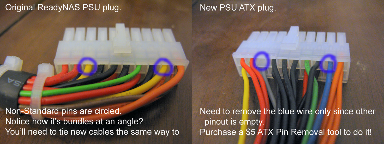
ReplyDeleteWhen I was searching for info on how to change the wires around, I never got a straight answer and the pictures are poor for the details I needed. So I will illuminate the cloudiness of this mod for the Ready NAS NV+ for all of you who have questions.
What you need to know is that ALL the yellow and yellow/black wires come from the exact same location soldering point on the PUS's circuit board. Just pull out the blue one and put any yellow or black/yellow wire in the 2 spots (the blue wire you took out and the blank spot.
I also clipped off all the other wires you don't need and organized them then put a bit of shrink wrap on each one to keep things from shorting out and just wrap them up neatly into the bundle. You don’t have to do this but there is not much room under there to hide them all and I’d rather have the air flow.
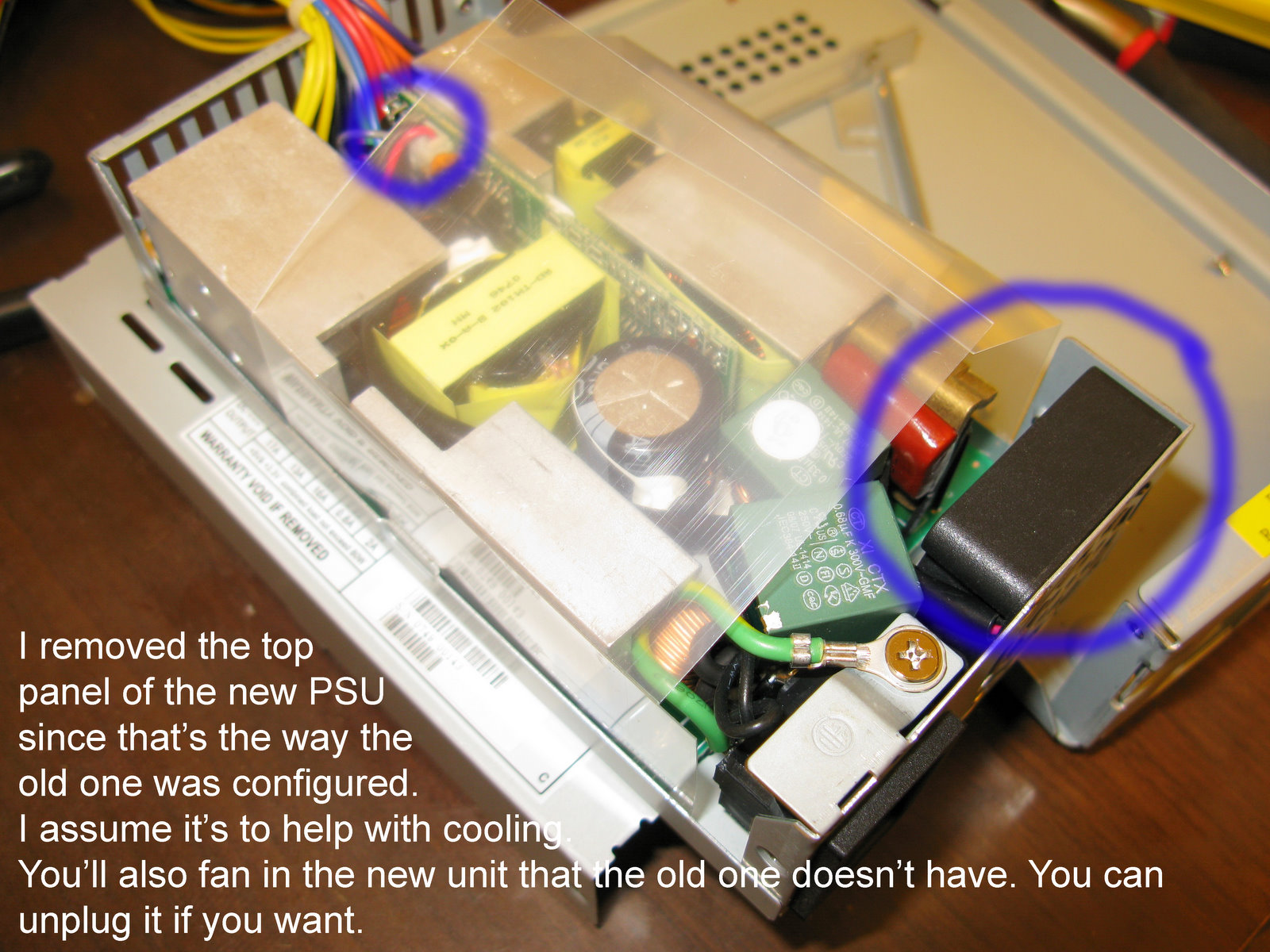
The clear plastic air diffuser I put back and it stays in place just fine if you put it in after you assemble the bottom half. You should have plenty of cable length to make it work.
I also cut out the back grill for the fan on this and put on a standard external grill for the 40mm fan.
I use a dermal to make a hole in the back of the NAS's bottom plate to line up with the fan. It is very quiet FYI and the HDD' are much louder than it.
2 staples, each with one side bent strait and then slipped down the sides of the pin, and a small drill bit worked great to push it out, DO NOT PULL, and took me all of 2 minutes to swap the pins. Make sure the paperclips are ALL the way down and push the wire up a bit and the clips down a bit more, and then push it out with the drill bit. I actually used something else I had laying around but anything will work great as long as it’s the right size to fit in the hole but not into the pin.
If you wish, you can swap out this fan when it dies or to be fancy or just because the fan is making noise, some reviews have this issue, mine didn't but yours might.
Buy the Notua 40mm fan NF-A4X10-FLX 5V here.
https://www.amazon.com/gp/product/B00NEMGCIA/ref=oh_aui_search_detailpage?ie=UTF8&psc=1
I also replaced my 80mm fan as well with a NF-B9 redux-1600
https://www.amazon.com/gp/product/B00KF7OMTI/ref=oh_aui_search_detailpage?ie=UTF8&psc=1
So far my temps are lower by 4*F by doing this fan mod to keep the 40mm and swap the 80mm. its nearly silent and the HDD's are louder than the entire system too.
Remember to replace a HDD every 2 years so that you always have a fresh drive and the oldest is at most 5 years MAX, unless you don't care about your data that much. I DO. Make sure you use RED HDD's RPM's do not matter.